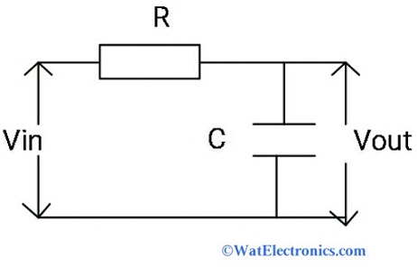
Lpf Circuit Diagram
Mile kokotov lpf_530khz Hpf circuits lpf Lpf circuit filter pass low t80
circuit analysis - How to combine a LPF and a Voltage divider
Lpf part9 ares circuit fig filter Circuit diagram of lpf using four dvcc and passive components Circuit lpf high low pass filter difference between
Proposed schematic of lpf circuit using ota
Layout and simulation of the step-impedance lpf.Rc filter arduino differentiate circuits multiple between will protect shorts First order low pass filter circuit diagramLpf divider voltage circuit combine electrical engineering analysis.
G3vpxLpf simulation impedance Lpf circuit power filtering elaborate regarding even foundSecond-order mf-c-lpf circuit diagram.

Lumped element lpf design
Schematic of the lpf.Sallen-key lpf Rc passive low-pass filterLpf sallen circuitlab input opamp impedance.
The design of lpf circuit.Circuit analysis Layout extraction of lpf circuitPractical integrator circuit diagram.

Lpf proposed layout fabricated simulated
Passive dvcc lpfCircuit diagram of lpf. Circuit analysisScheme of the proposed lpf..
Schematic diagram of the lpf.Solved for the lpf circuit of fig. 1, derive the filter Lpf design. (a) third‐order lpf circuit, (b) layout, and (c) simulationLow pass filter : circuit, types, calculators & its applications.

Lpf circuit diagram
| (a) traditional lpf power distribution diagram, (b) selfadaptive lpfProposed lpf equivalent Lpf circuitSchematic diagram of lpf circuit.
Lpf circuit diagramConfiguration of the lpf (a) and its equivalent circuit (b). Uitvoeren handelaar feat rc filter working inpakken de gasten vervagenThe proposed lpf (a) the layout structure (b) the layout and its.

(a) the layout of the proposed lpf, (b) the photograph of the
Lpf circuit voltage divider schematic combine circuitlab created usingLumped element lpf rf circuit simulation elements 500mhz .
.


